Desk & Chair Design with Topology Optimization (2022.03)
When performance and lightweight converge
Project Background

Project Objectives:
Design a topology-optimized desk and chair suit with dimensional, material, and loading requirements.
Design Constraints Given:
Desk length-height-depth limit: 60-30-25 in. It must be made of Nylon.
Chair minimum loading requirement: 150 kg. Also must be made of Nylon.
Computational Resources Involved:
Altair Inspire. It had a unique “wrap” function within the topology optimization module. This allowed the designer to have greater control of the appearance and aesthetic quality of the final product. Also, Inspire had a unique capability to create a lattice version of a solid design. This allowed lightweight designs to be achieved from a new perspective.
SOLIDWORKS. It was used to create the suit assembly and a studio view for my design.
Step 1 — Defining Raw Model, Design Space, and Loading Conditions

Defining the raw models properly ensured the design would be compliant with the dimensional requirements. Simple features (like the rectangular subtraction at the lower portion of the raw chair model) were added to the model to help direct the optimization process in alignment with the designer’s expectations. The dimension for the desk was 60-30-24 in. (length-height-depth). The dimension for the chair was 31-49-20 in. (length-height-depth).
Defining the design space (red) ensured that only those volumes were going to be modified during the optimization process. Reasonable shape control constraints (like symmetric constraints) were adopted for a more speedy optimization process.
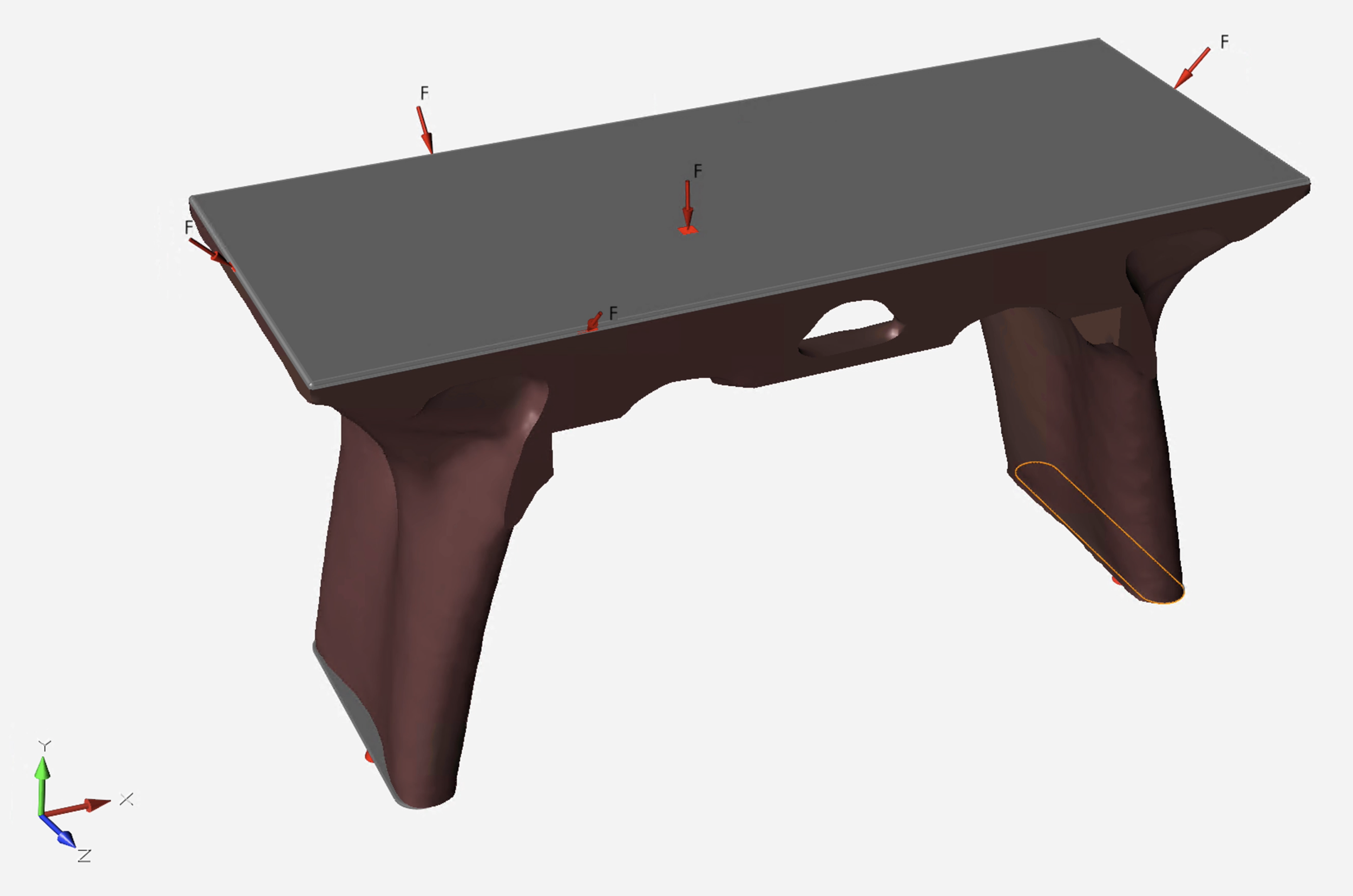
To run an FEA or an optimization study, we must first specify loading conditions and constraints. The loading conditions and constraints used for the desk were:
A 662 lb (300 kg equivalent) load was uniformly distributed on the top surface, pointing in the -Y direction.
Two loads with 662 lb each were uniformly distributed along the longer edges of the desk surface. They were 45 degrees above the X-Z surface.
Two loads with 331 lb (150 kg equivalent) each were uniformly distributed along the shorter edges of the desk surface. They were also 45 degrees above the X-Z surface.
All five loads were applied simultaneously (the extremest case verified).
Fixed constraints were applied to the lower surfaces of two flat foot pads.
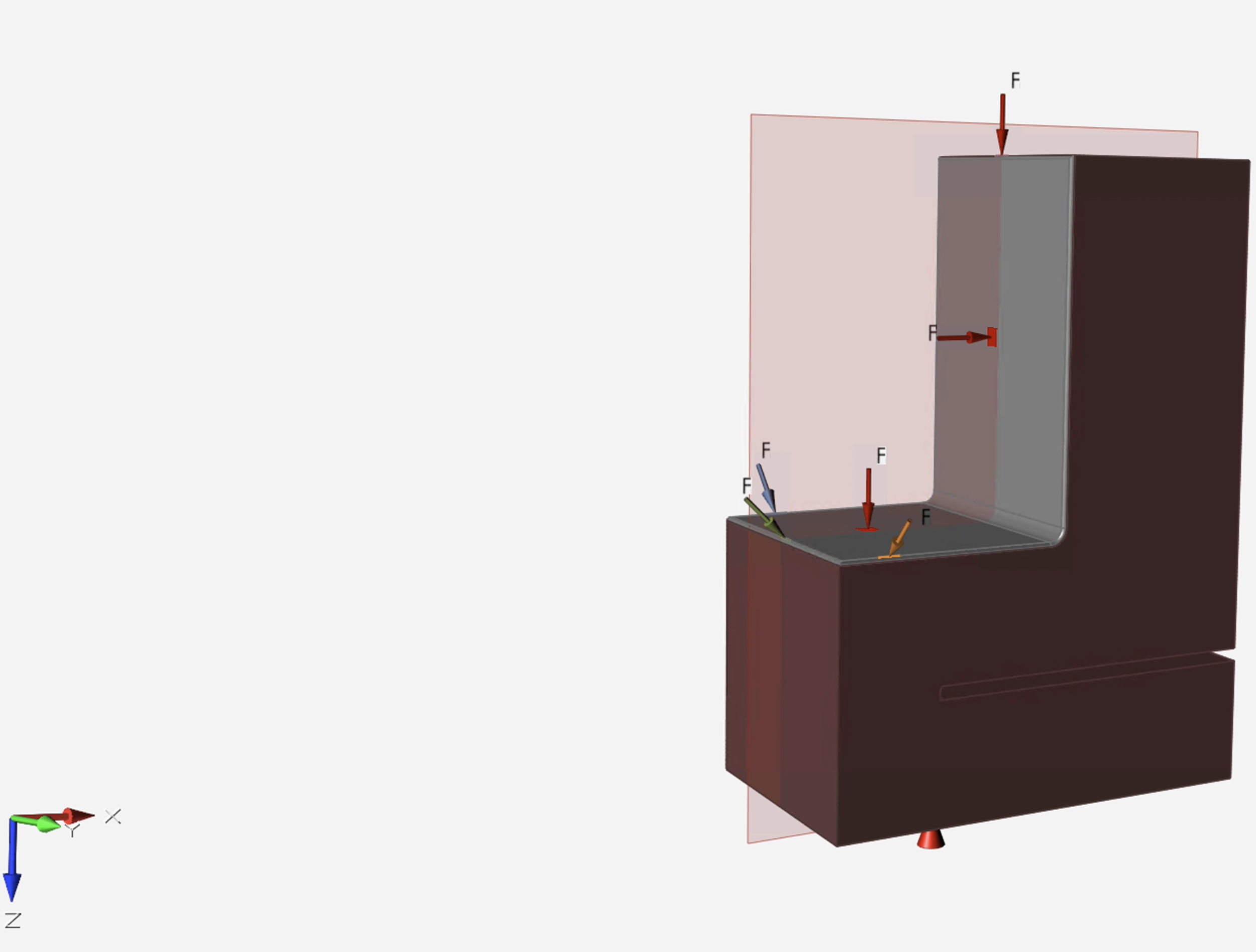
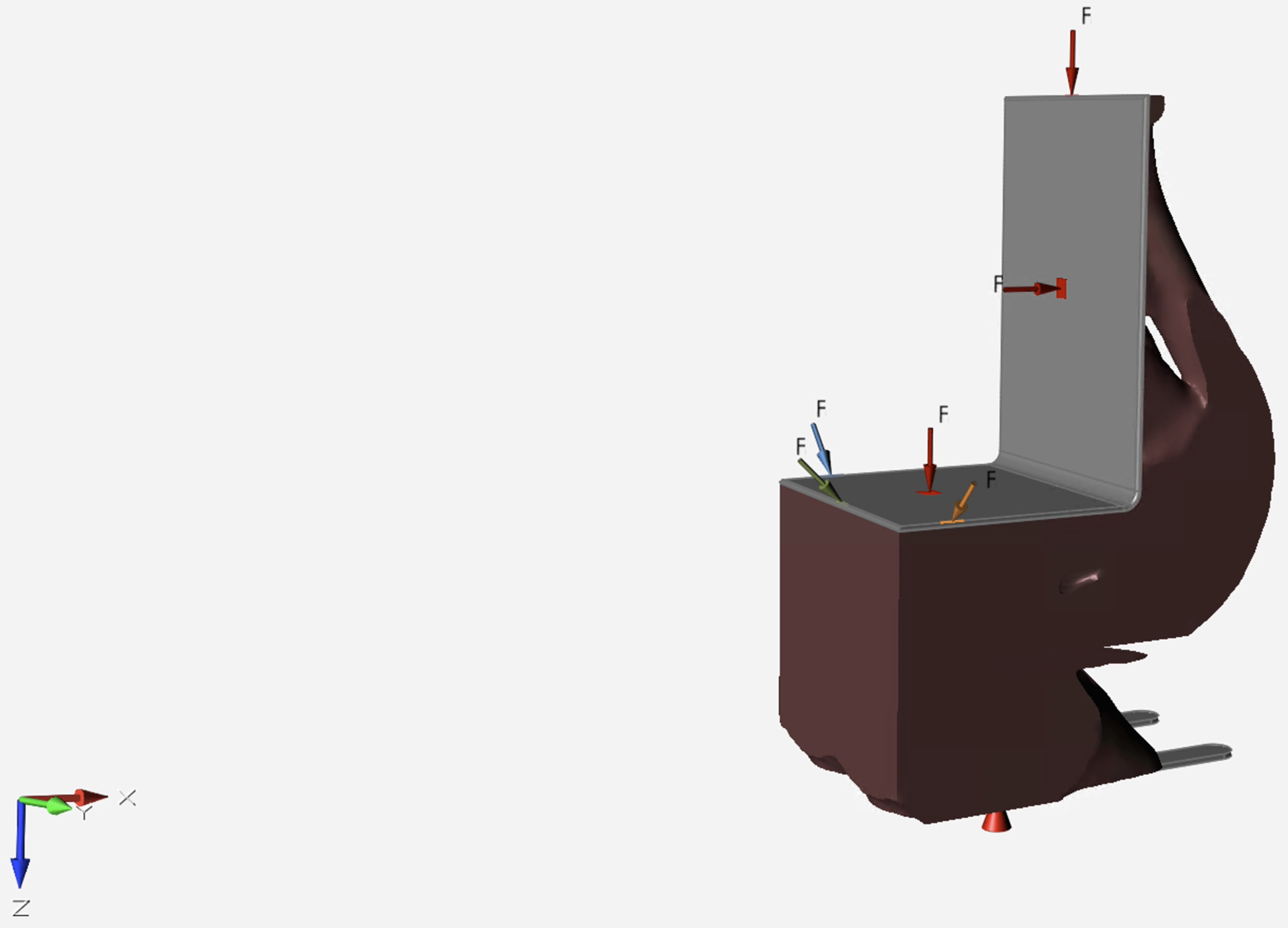
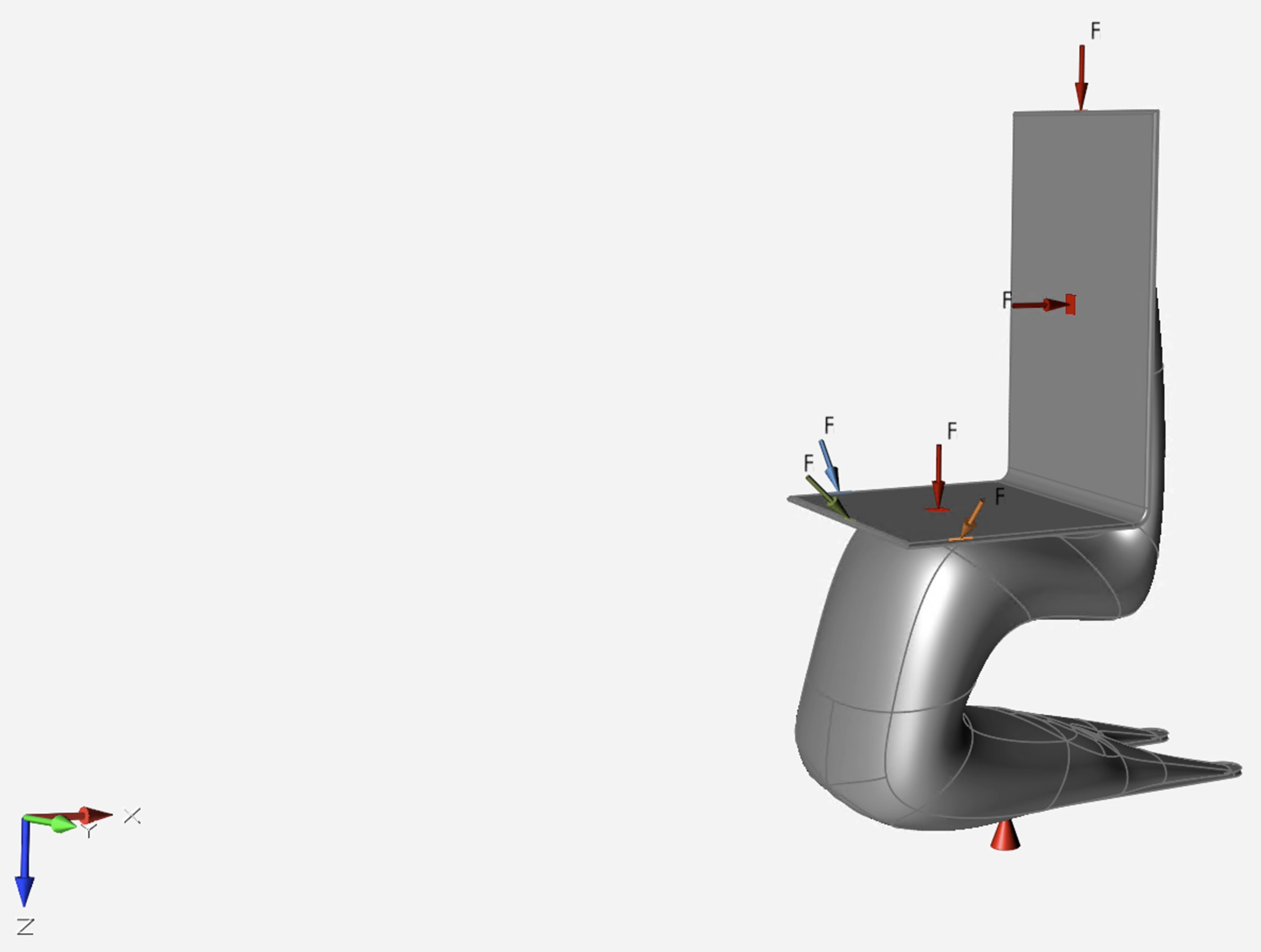
The loading conditions and constraints used for the chair were:
A 662 lb (300 kg equivalent) load was uniformly distributed on the seat plate surface, pointing in the +Z direction.
Two loads with 331 lb (150 kg equivalent) each were placed on the seat back. One of them was uniformly distributed along the upper edge of the desk surface in the +Z direction. The other was uniformly distributed on the back seat surface in the +X direction.
Three loads with 662 lb each were uniformly distributed along three edges of the seat plate surface. They were also 45 degrees above the X-Y surface.
All six loads were applied simultaneously (the extremest case verified).
Fixed constraints were applied to the lower surfaces of two flat foot pads.
Step 2 — Performing Optimization Study
The optimization studies were performed to maximize stiffness while achieving a 30% mass reduction (self-set target, as the minimizing mass strategy may result in large strain). Mesh size was set to a moderate level to balance accuracy and process duration. Gravity was considered in this study.
It was, however, not hard to see that the software-optimized products were not visually appealing.
Step 3 — Improving the Delicacy of the Optimized Models
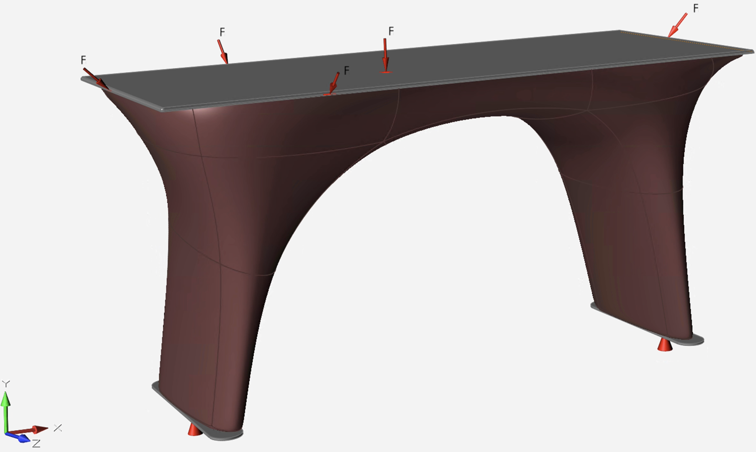
With the use of the “wrap” function and treating the original optimized models as a design guide, we could create segmented bodies with smooth appearances and connections. Once being created, a body segment would automatically connect and blend with all other body segments.
FEA was performed on both designs, and the factors of safety were determined.
The table had a minimum factor of safety of 3.4.
The chair had a minimum factor of safety of 7.3.
Step 4 — Achieving Additional Weight Reduction

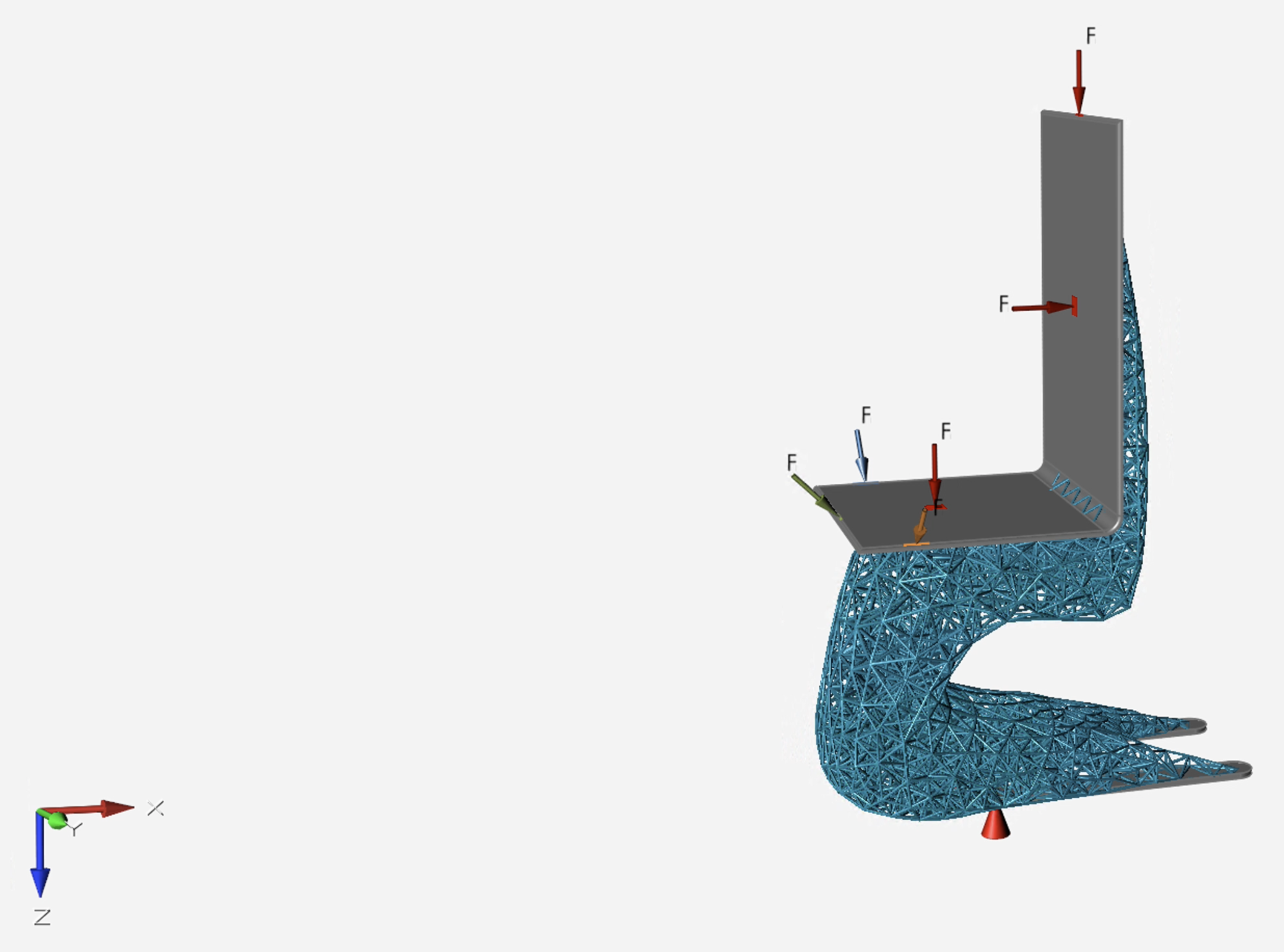
Additional optimization studies were performed to turn the design space into lattice structures so that the model weights could be minimized. Lattice lengths and diameters were set to a moderate level to balance efficacy and process duration. Gravity was considered in this study.
After performing weight analysis and FEA, the following information was obtained:
The table achieved a weight reduction of 92.3%, while its minimum factor of safety dropped to 2.5.
The chair achieved a weight reduction of 88.9%, while its minimum factor of safety dropped to 2.2.
The Final Design


A design that blends functionality with delicacy.