Programmable 3D Food Printing (2022.04)
High-precision 3D printings achieved from scratch
Project Background

Project Objectives:
Extrude various types of food materials through a simple custom-built “3D printer” to precisely construct structures with complex geometries.
Physical Resources Involved:
Various food items. The food items were self-sourced and then verified.
The simple custom-built “3D printer.” The printer could read G-code only. The printer had a 3 DOF movable platform that could house two syringes simultaneously. Syringe barrels must be manually loaded or released, but motors were installed on top of the movable platform to push the plungers automatically. There was no heating mechanism or force sensor installed on the printer.
Syringe barrels, tips, and plungers. These were standardized supplies and were provided.
Microwave. It was used to heat refrigerated food items or those that required mixing at a higher than room temperature environment.
Computational Resources Involved:
Python. Using nested loops in Python, one hundred lines of Python code could almost instantly generate thousands of lines of G-code. This allowed easy modification of geometric shapes and parameters.
G-code. Each line of G-code was used to change the machine setting or to instruct the movable platform to move to the next point in a specific way while extruding a particular amount of material.
For example,
G21
G90
G1 X25 Y50 Z100 E2 F300
The Major Challenge — Mysterious Food Materials

Lavish Amount of Choices:
There are hundreds of types of food materials available on the market. An ideal food material for this project should be in a liquid state at room temperature. It also should have a shear-thinning property for easier extrusion and firmer support. Some of the materials acquired and tested include chocolate cookie dough, cream cheese, cheese sauce, frostings (chocolate & strawberry), pressurized cream (w/wo cane sugar powder), milk chocolate, marshmallows (self pre-heated), and peanut butter.
Limited Mechanical Properties Known:
The manufacturers of most food materials are not required to disclose the mechanical properties of their products. Therefore, critical information like viscosities at different temperatures or shear rates remained unknown.
Dynamic Filament Geometries Influenced by Many Factors:
Material type. As illustrated in sub-figure a, while all other conditions are the same, the extruded filament from different materials may have drastically different cross-sectional geometries.
Extrusion quantity E between two points. As illustrated in sub-figure b, while all other conditions are the same, a linear increase with E resulted in drastically different geometries.
Z-axis offset from base/previous layer. As illustrated in sub-figure c, while all other conditions are the same, a too-large Z-axis offset value would result in a zig-zag-shaped filament.
The temperature of the material at extrusion. As illustrated in sub-figure d, while all other conditions are the same, the filament extruded at different temperatures may have drastically different cross-sectional geometries.
The limited extruding power. Theoretically, with a constant distance between two points and a fixed extrusion quantity E, the faster the feed rate F (speed of platform movement), the higher the extrusion flow rate and power requirement. However, the extrusion motor has power limitations, and thus the extrusion flow rate should have a maximum threshold.
The Attempt to Establish a Mathematical Model
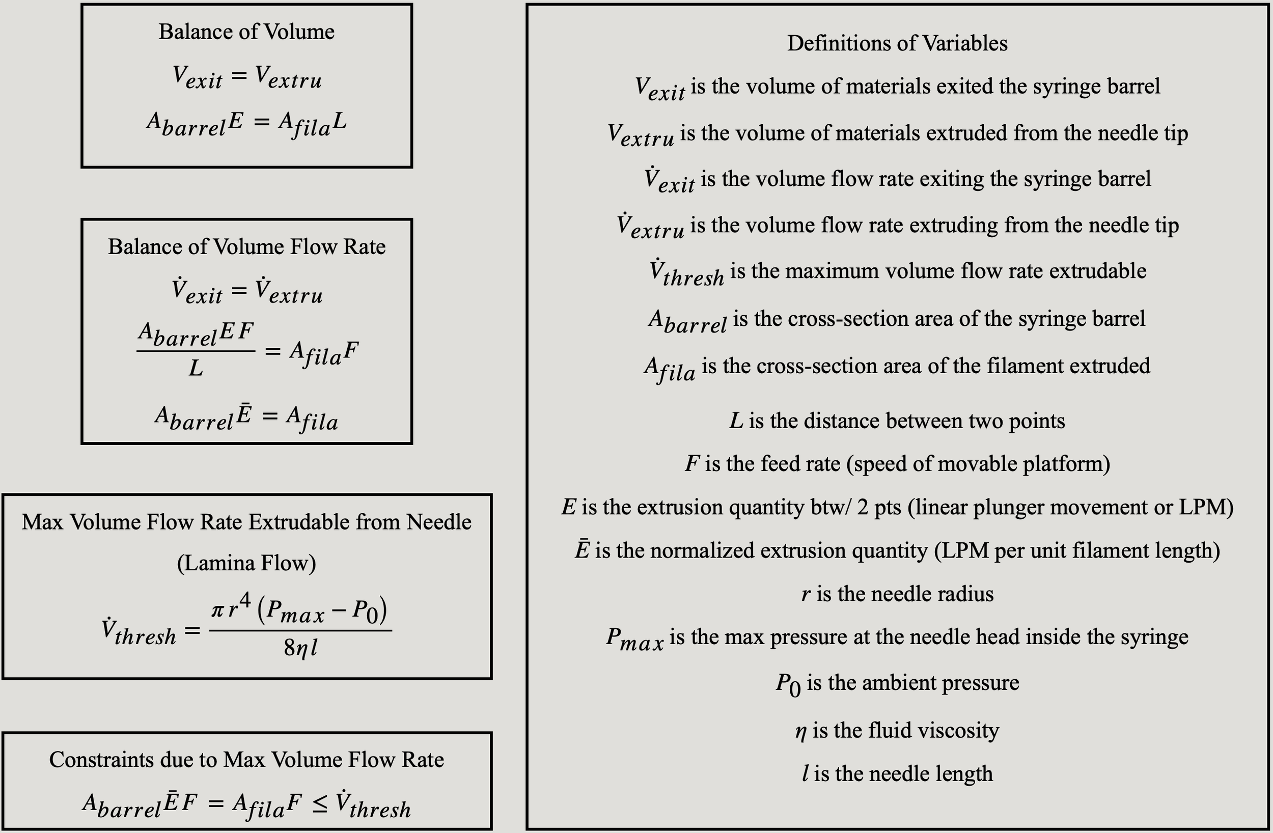

To estimate the raw material usage (during the production planning stage), preview the final product, and understand the production system’s limitations, it would be necessary to construct mathematical models to describe a manufacturing process.
Therefore, the four models in the upper right section were established to help understand the 3D food printing process better:
The Balance of Volume Model. The volume of materials that exited the barrel should be equivalent to the volume of materials extruded from the needle tip. This model would be practically useful if the geometries of the cross-sectional area of the filament are clearly defined.
The Balance of Volume Flow Rate Model. The volume flow rate of materials exiting the barrel should be equivalent to the volume flow rate of materials extruding from the needle tip. This model would be practically useful if the geometries of the cross-sectional area of the filament are clearly defined.
The Maximum Extrusion Flow Rate Model. The maximum flow rate allowable to be extruded from the given printer could be approximated by the needle length and radius, the pressure at both sides of the needle, and the viscosity of the material. This equation could also be used to monitor the system volume flow rate over time (just change Pmax to Pt).
The Model Describing Constraints Posed by The Maximum Extrusion Flow Rate. The volume flow rates of materials exiting the barrel and materials extruding from the needle tip should both be less or equal to the maximum flow rate allowable to be extruded from the given printer. The figure in the lower section illustrated a case where the filament area has failed to be maintained at 30 mm when F exceeds 10 mm/s. This is because the max extrusion flow rate has already been reached at F = 10 mm/s.
After deriving the models above, I realized that due to the complications stated in the previous section, defined filament geometries and critical material properties were unavailable. Also, as there were no force/pressure sensors mounted in the system, nor was there any motor specification provided, it was not possible to find the pressure value at the inner tip of the needle. Therefore, at that time the mathematical models were not very practically useful in the subsequent design and manufacturing process.
Nevertheless, this provided a deep and clear insight into how a matured 3D printer (like an FDM printer) on the market was designed and controlled. Additionally, once in the future food materials with defined cross-sectional geometries and mechanical properties are found, or there are force/pressure sensors installed on the printer or in the syringe, these models should become more useful.
Design & Manufacturing Process Overview


Due to the lack of available information, a calibration-test-based design and manufacturing process was adopted. The process is summarized below:
Perform print calibration test using the base section material and determine a good initial Z-axis offset height for extruding the first layer. The extrusion quantity E between two points can be set at any non-extreme value as long as the filament is continuous. The feed rate F should be set at a low value, such as 50 mm/min or 100 mm/min. Verify that the extruded filament is straight but not zig-zag-shaped.
Maintain the determined Z-axis initial offset, and set F at a low value. Try out a variety of E values on a filament with a fixed length (e.g., 10 mm) and find an E value that would produce the ideal filament (e.g., a relatively wide filament with a smooth top surface). Now, we can calculate the normalized version of the ideal E value (linear plunger movement per mm filament). Using normalized E value ensures filaments with different lengths have similar cross-sectional geometries like width.
With the same fixed-length filament, try out multiple higher F values. Pick a high F value that does not result in a decrease in filament cross-sectional area (width can be an indicator).
Measure the geometries of a filament constructed using the determined E (normalized), F, and initial Z-offset values. Use the height of the filament as the subsequent layers’ Z-offset values. Slightly adjust the parameter values if needed.
Repeat the procedures above for layers made from other materials. Make sure to align the geometries of the filaments made from different materials.
Use the measured geometries to perform product design.
For rotational structures, use 2D coordinate transformation laws. Make sure to balance magnificence (large rotational angle) and structural stability (small rotational angle).
For structures with diminishing geometric values, make sure to balance simplicity (large parameter reductions, fewer layers required) and structural stability (small parameter reductions).
For structures with the use of time-dependent functions (lengths between points are drastically different), determine the distance between each of the two points. Use the normalized E value to calculate a tailored E value for every distance.
Use nested structures to increase structural stability if needed.
Twisted Pyramid — Single Material

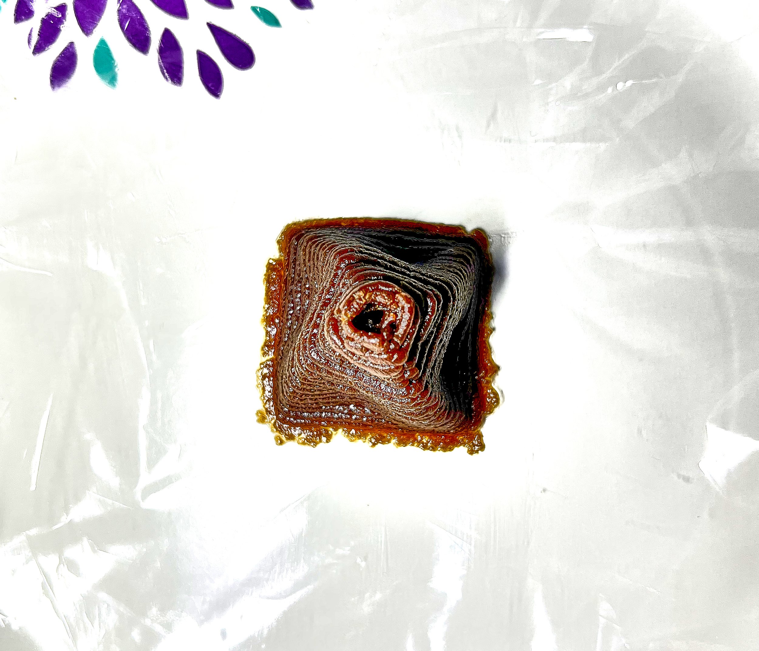
Material Used:
Chocolate cookie dough
Advantages of the Material:
Relatively high stiffness (low compressive strain at lower layers, layer boundaries are still clear).
Relatively fast solidification (loss of water) in the open air (further increased stiffness + reduced intra-structural load).
Disadvantages of the Material:
Less appealing color.
Viscosity was too high at room temperature, and thus required heating for smooth extrusion.
Relatively poor adhesion between layers, and thus some squeezed horizontal offset occurred.
Structural Parameters:
Two nested squares at each layer. The outer square was 30-by-30 mm, and the inner square was 27-by-27 mm.
There were 24 layers of rotating squares in total, each with 1.1mm of side length reduction, 1.25 mm of inter-layer Z-axis offset, and 1.5 degrees of inter-layer rotational offset.
E of 0.55/0.50 mm for the outer/inner square at the base layer, with a reduction of 0.02 mm for each subsequent layer. The normalized E value was 0.0183 mm LPM per mm filament.
Twisted Pyramid — Two Materials


Material Used:
Cream cheese (base layers) and processed cheese sauce (top layers).
Advantages of Cream Cheese:
High stiffness, low density, good adhesion, moderate viscosity at room temperature, and elegant color.
Disadvantages of Cream Cheese:
Somewhat hard to extrude at low temperatures.
Advantages of Cheese Sause:
Similar to those of cream cheese.
Disadvantages of Cheese Sause:
Relatively low stiffness (inter-layer overrun and diminishing layer boundaries over time).
Structural Parameters:
Two nested squares at each layer. The outer square was 30-by-30 mm, and the inner square was 27-by-27 mm.
There were 24 layers of rotating squares in total, each with 1.1mm of side length reduction, 1.25 mm of inter-layer Z-axis offset, and 1.5 degrees of inter-layer rotational offset.
E of 0.55/0.50 mm for the outer/inner square at the base layer, with a reduction of 0.02 mm for each subsequent layer. The normalized E value was 0.0183 mm LPM per mm filament. These could be applied to both materials.
The Diamond — Three Materials Spirograph


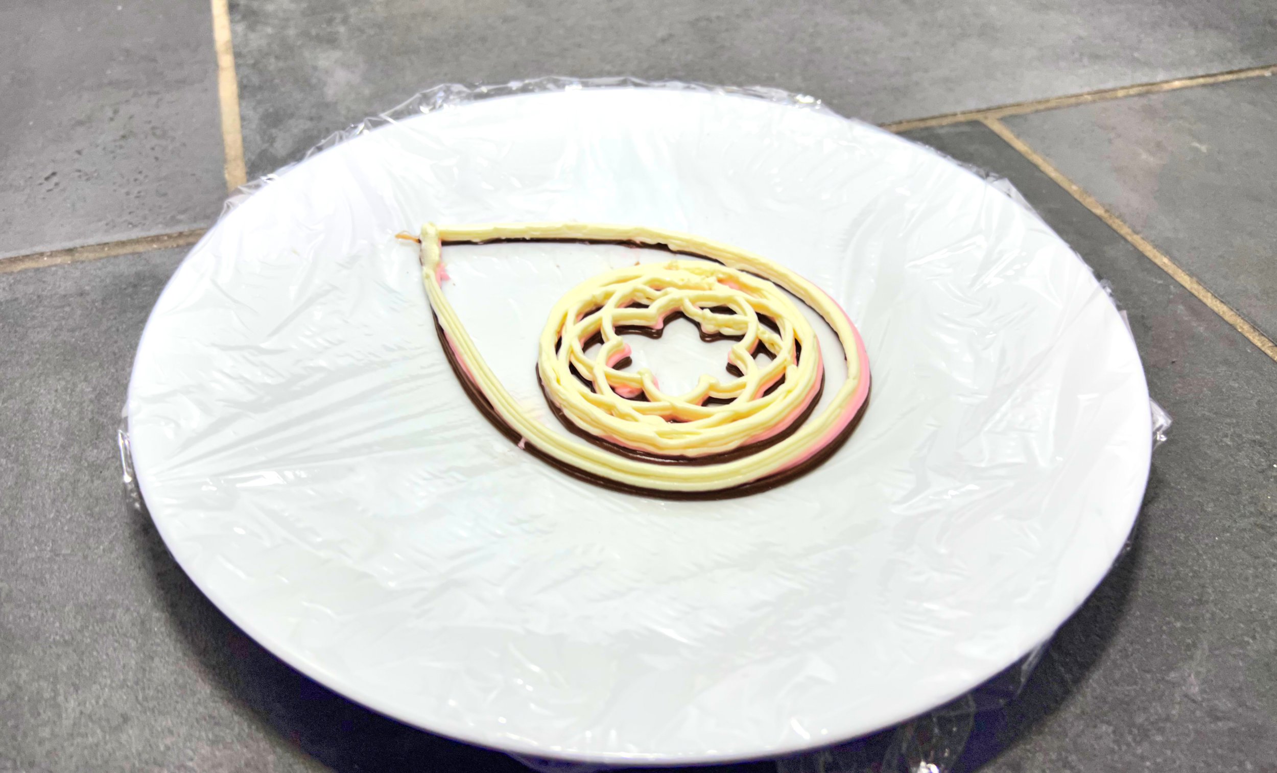
Material Used:
Chocolate frosting (base layers), strawberry frosting (middle layers), and cream cheese (top layers).
Advantages of Frosting:
High stiffness, low density, good adhesion, moderate viscosity at room temperature, and appealing color.
Disadvantages of Frosting:
Extrusion parameters varied dramatically from one brand to the other due to differences in ingredients and formula.
Structural Parameters:
This print consisted of an epicycloid enclosed within half of a Bernoullian lemniscate. Both of the shapes were described by time-dependent functions. Therefore, distances between points varied significantly.
The epicycloid had a base circle radius of 15 mm and a rolling circle radius of 12.5 mm.
The lemniscate had a tip-to-end length of 150 mm.
The print had 7 layers in total. Three top layers were cream cheese, two middle layers were strawberry frosting, and two base layers were chocolate frosting.
The normalized E value for cream cheese in the epicycloid was 0.0145. The normalized E value for frosting in the epicycloid was 0.0181.
The normalized E value for cream cheese in the lemniscate was 0.0227. The normalized E value for frosting in the lemniscate was 0.0253.
Creation of the Diamond
A 60-second insider tour into the world of 3D food printing