Robotics Studio - The Ultimate Turtle (2022.9 - 2022.12)
Speed and shell in perfect harmony
Project Background

Project Objectives:
Design and manufacture a quadrupedal robot that could walk as fast as possible with an as large as possible effective cargo volume. Speed points are assigned in value multiplier style, while cargo volume points are assigned upon reaching thresholds. The speed goal was set by myself at 35 cm/s.
Design Constraints:
The robot must be “organic,” with as few sharp edges as possible.
The cargo volume needs to be enclosed and well-protected.
The design may only utilize the following supplied parts without substitution: eight serial bus revolute servomotors (2.94 Nm), one rechargeable battery, and one Libre Le Potato single-board computer.
Manufacturing Constraints:
May only use a 3D FDM Printer with a build volume of 280*250*300mm (L * W * H) to produce parts in PLA.
Computational Resources Involved:
Siemens NX. It was used to create and analyze the 3D CAD robot structure. Functions used include modeling, drafting, assembly construction, finite element analysis, and motion simulation.
Python. This was used to write and execute codes to control robot gait.
Ubuntu OS. This is a Linux-based operating system used in Libre computers.
Step 1 — Defining Robot’s Shape & Core Parameters

Body Shapes:
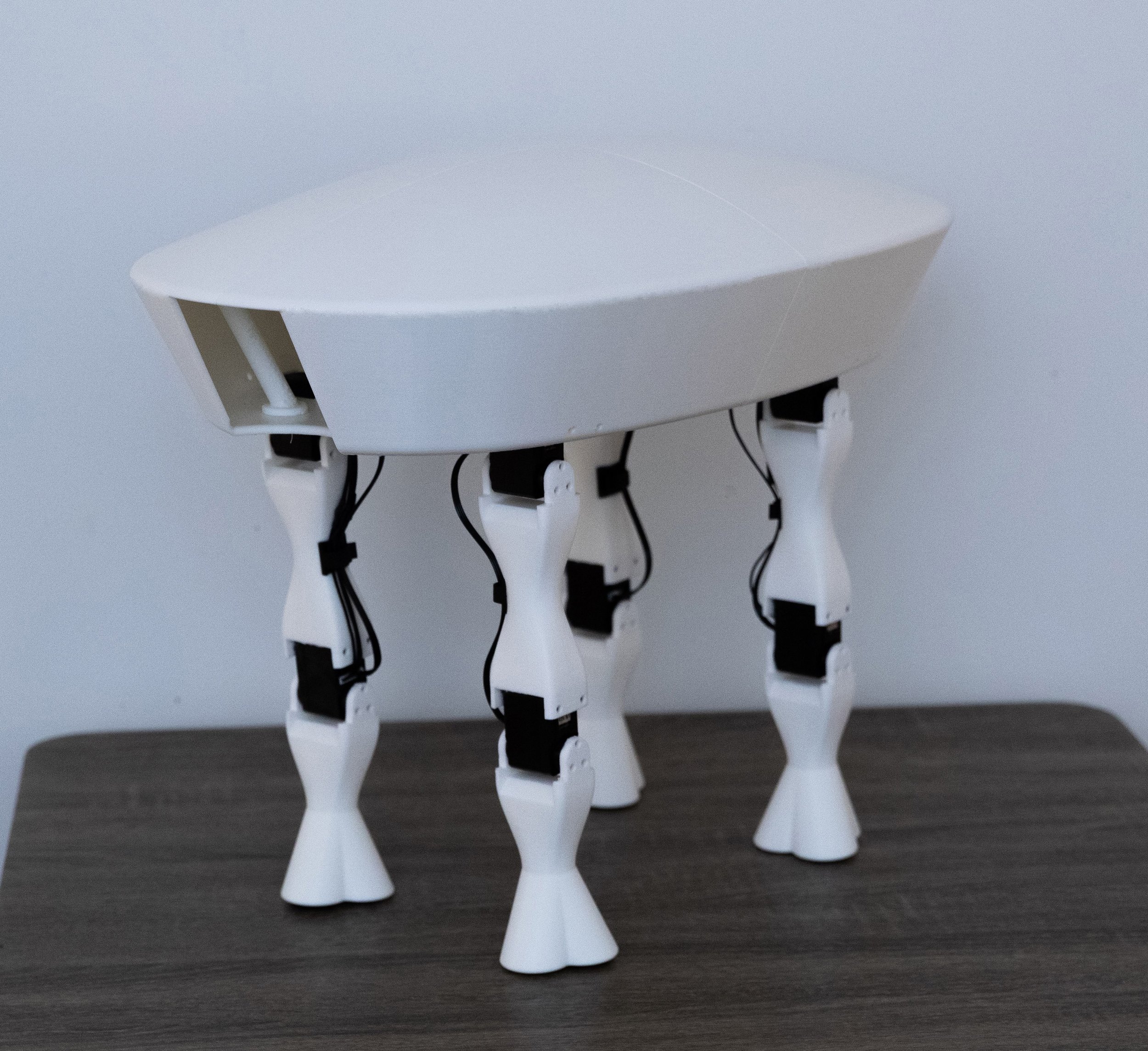
After exploring various design inspirations, it became clear that a sea turtle's body shape perfectly aligned with my project goals: substantial cargo capacity achieved in a natural, organic form. By incorporating efficient motors and a well-crafted structural design, this turtle-inspired robot could achieve impressive speeds, defying conventional expectations. The concept also resonates with my earlier scallop sampling preliminary design project, demonstrating a progressive evolution in my design journey.
Body Parameters:
The turtle-inspired body design features a dominant dimension — length, where L << W < H is typically observed. As the most significant loadings (gravity & response) are in the body's height (H) direction and the body is most prone to bending, the 3D printed layers should lay in the L-W plane that is perpendicular to the H direction. To maximize cargo volume per print, the robot's length (L) should be as close to [a multiple of (280-5)] mm as possible, considering the build plate dimension of 280*250mm. Two concept designs were proposed, with lengths of 275mm and 550mm. Each design showcases a distinct L-W-H ratio, derived from the max volume approach (until the largest volume category is achieved), as well as aesthetic and balance considerations (with increased W and decreased H).
Leg Parameters:
To preserve the organic and seamless appearance of the robot's body, legs were positioned at the base. For improved balance, they were placed as close to the corners as feasible. Drawing inspiration from cheetahs (with a 60% LL-BL Ratio) and factoring in leg placement, the LL for both concepts was set to 50% of the BL.
Concept Verifications:
Basic CAD models were created for both concepts to estimate their mass. Verification involved a static balance test (with a self-designed 10N force applied at the body's centroid, directed towards the most vulnerable standard orientation) and a dynamic straight 60° gait analysis. This particular gait was chosen for its simplicity, relative stability (more horizontal movement per unit motor angle change than vertical), and its ability to provide a realistic (very similar to human gait) preview of the minimum motor torque required for the more torque-demanding diagonal two-leg stand-off. It's important to note that the minimum stand-up torque needed for a straight 60° gait is indicative of the minimum stand-up torque required for a zig-zag gait initiated from a resting position.
Concept Selection:
Both concepts satisfied the top cargo volume requirements. Concept 1 was superior in torque reserve (60-deg straight gait stand-up with 0.75 Wbody leg placement). Meanwhile, concept 2 had greater static stability and left more room for design changes to meet other requirements. Thus, concept 2 was selected.

Step 2 — CAD Design & Analysis


Modeling and Assembly Creation:
All structural components were designed using Siemens NX, adhering to the geometric requirements mentioned in the previous section. Multiple levels of assemblies were created to maximize flexibility in the event of structural changes. Care was taken to ensure no interference occurred between static structures. Special design considerations included:
Prioritizing an organic and seamless design.
Incorporating cable plugs in the assembly to prevent any port blockages.
Adding rails for adjusting component racks, enabling fine-tuning of the COM locations.
Integrating connection plate design into the component racks to reduce structural complexity, as the loading requirements were limited.
Drafting:
Technical drawings for the robot were generated, featuring multiple views, key dimensions, and a comprehensive bill of materials.
Finite Element Analysis:
Upon completing the draft design, several FEA tests were conducted:
The maximum stress in leg segments was examined, assuming the application of maximum motor torque and max axial and shear forces. A weak geometry was identified in the motor mounting clamps, leading to the implementation of a thicker design for this structure.
FEA was performed on the robot body, assuming it’s in a standing straight configuration, with a 50 N extra load applied to the robot base. Weak geometries were discovered at the battery racks, prompting the adoption of a stronger design.
Step 3 — 3D Printing & Assembling
3D Printing of Structural Components:
All structural components were fabricated in PLA using an FDM printer. Throughout the manufacturing process, I paid close attention to the following details:
Ensuring the print layers were perpendicular (part prone to bending) or parallel (part prone to fracture or buckling) to the principal loads applied on the components.
Double-checking that no support structure was added to small recessed features.
Examining the print simulation page and confirming that adequate and high-quality support structures were generated for all large overhangs.
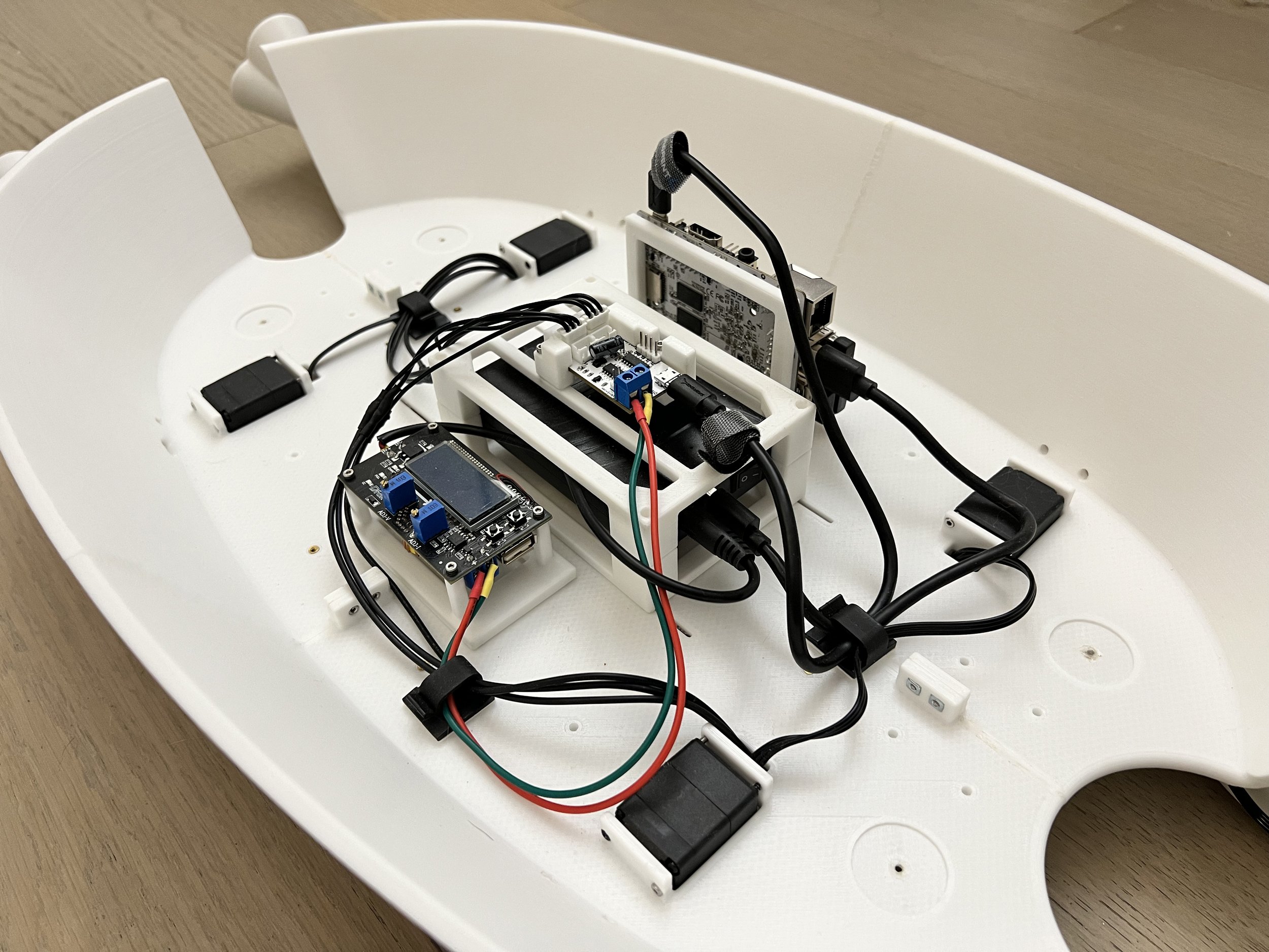
Overall Assembly:
All structural components were assembled using screws, nuts, and thermoplastic inserts. Additionally, all power and signal cables were correctly connected. Throughout the assembly process, I paid close attention to the following details:
Ensuring that all exposed wires were covered, typically by employing heat shrink tubes.
Confirming that cables were collectively managed using appropriate constraining devices.
Making sure all mechanical connections were tightened, with no loose structures present.
Step 4 — Gait Exploration & Time to Walk!
Walking Pattern Chosen:
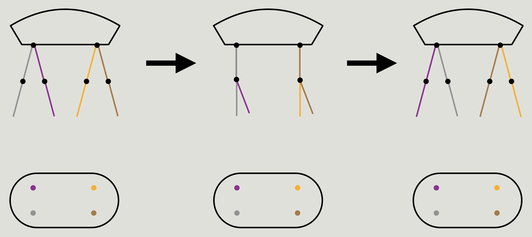
The selected walking pattern was inspired by human locomotion. To illustrate a sample gait pattern, let's use the grey and purple legs shown above as an example:
The grey leg executes a straight 30° counterclockwise gait (frames 1-3).
The grey leg transitions into the purple leg in frame 1. The upper motor rotates 15° clockwise, while the lower motor moves 20° counterclockwise (frames 1-2). The upper motor then rotates another 15° clockwise, as the lower motor reverses 20° clockwise (frames 2-3).
The purple leg in frame 3 reverts to the grey leg in frame 1, and the cycle continues.
To enhance the stability of this bio-inspired gait, it was crucial to establish a large base of support (BOS). This approach ensured that the margin of stability (MOS) remained mostly positive, even when the COM movement was significant. A triangular lower-leg design was developed to satisfy the organic requirement while balancing the gait stability and design bulkiness.
Performance Evaluation:
The gait proved to be stable and uninterrupted. The robot achieved a maximum speed of 37 cm/s, surpassing my initial goal. The effective cargo volume far exceeded the threshold required for the highest point category attainable.
The total points earned amounted to 135, an impressive 82% higher than the class average of 74 points.
Although a fast-walking robot has been successfully developed, numerous opportunities for improvement remain. Potential future research areas include:
Investigating the turning mechanism to determine the feasibility of controlled turning.
Exploring the cheetah-inspired zig-zag gait to evaluate its potential advantages.
Utilizing robotic learning techniques to optimize the robot's gait.
Implementing weight reduction strategies for the robot's body, as enclosed cargo area requirements are no longer a constraint.